Electronics Production
Like last week this week also have two assignment one is group assignment and other one is individual assignment.
-
Group assignment:-
Characterize the design rules for your PCB production process
-
Individual assignment:-
Make an in-circuit programmer by milling and stuffing the PCB, test it.
Group Assignment
The Group Assignment page is at the following link.click here
The machine and the PCB production process
In my fablab for pcb milling/drilling monoFab SRM-20 is available.
Here is the few features of SRM 20
-
This machine can be used for PCB milling and drilling other than that this machine can also use for Cuttable Material of Modelling Wax, Chemical Wood, Foam, Acrylic, Poly acetate, ABS.
-
X, Y, and Z Operation Strokes203.2 (X) x 152.4 (Y) x 60.5 (Z) mm
-
Workpiece table size232.2 (X) x 156.6 (Y) mm
-
Distance From Collet Tip to TableMax, 130.75mm (5.15 in)
-
X-, Y-, and Z-Axis Drive System have stepping motor
-
Operating Speed is 6 - 1800mm/min
-
Spindle Motor is DC motor Type 380
-
Interface is USB
-
Cutting Tool Chuck with collet method
-
Spindle Rotation Speed can adjust i.e Adjustable 3000 - 7000 rpm
-
Dedicated AC adapter: AC 100-240 V ±10%, 50/60 Hz
Step by steps for PCB Milling on SRM 20:-
The work piece material is attached on a detachable plate which moves along the Y-axis. The drilling/milling tool is attached to the head which moves along the X-axis. The end mill is attached to a DC-motor (10 W) which is mounted on a carriage that allows the movement along the third axis, the Z-axis
- Turn on SRM 20 Monofab and Connect with usb interface to PC/laptop.
- It needs the trace (inner circuit) and cut (outline of the circuit) for the circuit with .png format.
- Create and save file of circuit board traces and out cut.
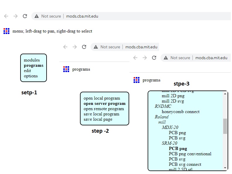
Prepare to create .rml file using mods
For printing in the SRM20 .rml file is required from conversion of .png file to .rml
file i have been going through the mods. The MIT mods site is https://mods.cba.mit.edu/
In 4th step it needs to change the x,y,z to zero and in home section z make to 5 mm.As manually
i will do the origin setting though the v panel.hence the .rml file creation time it need to care about set origin and home only
the z axis have to 5 mm. I did mistake at the time .rml file creation.i was putting it as zero hence it was getting wrong at the time of
end the milling job the time of milling.It was jut put a milling from the end to origin i.e z axis is not getting up after milling completion.
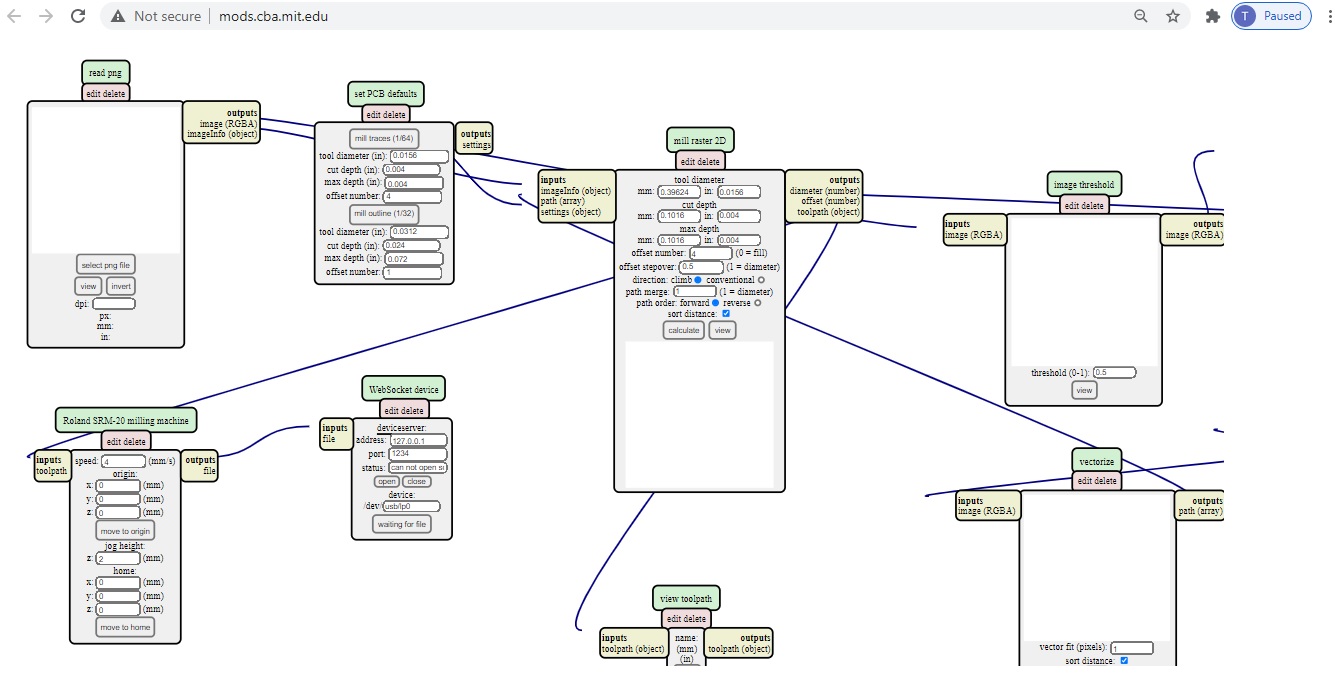

it needs to delete the websocket to the localhost i.e 127.0.0.1 where it have to to save file.
which can provide to save file to local system.
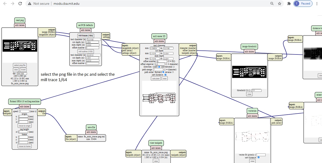
hen it very important to first save the.png file of both trace and cut for the circuit to mill the pcb.
Cut

Trace

For tracing mods calculation here it can be put the max milling using in
my SRM 20 maximum .005 mm. The x,y and z axis can also be defined.
.

After download the .rml file to the local system,
now we have to
install the milling bit i.e 1/64 for trace and 1/32 for cut.when ever install the bit to the SRM it should be carefully hold
by two finger otherwise any wrong may happen.


Now it needs to set
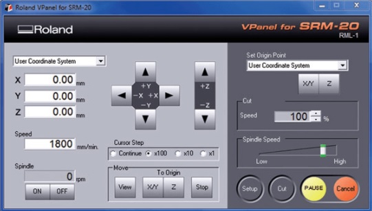
find zero for x, y, and z for this Milling Made easy with a User-Friendly VPanel
The SRM-20’s VPanel controller provides a simple interface for adjusting tool position
and moving the cursor to set the milling starting point. The VPanel also allows easy control
of feed rate and spindle speed with pause and resume operation, plus tracking of X,Y,Z axis milling with a numeric readout in millimeters or inche.
Now click on cut and delete previous file click delete all then select the .rml file and put cut.
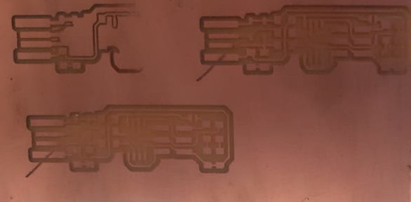
What i did wrong:-
Here three milling jobs have been given one by one but each one was a failure .
- For two jobs, after every completion of trace the milling the bit cross the job which not produce fruitful results here the job height in the home section in mods was set zero hence the problem comes i recertified to 5mm for job height in mods.Then the problem has resolved.
- One of the milling is only few areas is properly milled but other is not as the PCB is not properly leveled and fixed in the work piece in the bed.Again i remove pcb and put both adhesive paper and fix properly with proper level.
After trace and Cut:-
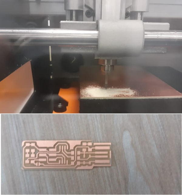
Once the milling job is completed it needs to remove the cut pcb and clean the SRM 20 and check whether the given trace is properly mill or not.
After milling, then it needs to do soldering.
Soldering the Circuit:-
Heat the soldering iron point the place where you need to put the component and put the solder just close to it as heat in copper layer then solder melts same time remove the solder then automatically solder will
deposit but it a fraction of a second but more practice for perfection and clean soldering
 Circuit Layout:-

 Required Component
- 1x ATtiny45 or ATtiny85
- 2x 1kΩ resistors
- 2x 499Ω resistors
- 2x 49Ω resistors
- 2x 3.3v zener diodes
- 1x red LED
- 1x green LED
- 1x 100nF capacitor
- 1x 2x3 pin header
The LEDs and their associated resistors are optional; the red LED lights when the target circuit is powered, and the green LED lights when the programmer is talking to the target.Solder the parts to the PCB, using the schematic and board imagebelow as a reference for component values and placement.Start with the most difficult parts (the ATtiny45) first, so you have the most access.Install the ISP header last, as it is large and can get in your way if you do it earlier.
 Check the Circuit after soldering:-
While it may seem early to start debugging already (we haven't even tried anything yet!) it is always prudent to check your work before plugging in a board. It only takes a couple of minutes and can save you headaches down the road.
Check your board against the schematic and PCB layout image to make sure that you have installed the correct components in the correct locations and orientations.
Inspect your board visually. Components should be flat on the board, not tilted with pins in the air. Solder connections should be smooth, and solder should have flowed both onto the pin and onto the pad. If you still see a lot of exposed copper on the pad, or the solder is lumpy and draws up into a point where you removed the iron, you probably don't have a good connection. Reflow by applying heat and flux (either from a flux pen or by adding a tiny bit more solder). Also look for unwanted solder bridges between nearby traces and pins.
Use a multimeter to check for shorts between VCC and GND

i have checked all the component as per the part diagram using multi meter its found ok
now its time for programming. As I am very much new to this topic lets try ....
Programming the Micro controller:-
I am very much new to Programming, But my instructor gave me a few ideas about microcontrollers and also told me to try in linux as i am using ubuntu so it will become easy.i referred the link for programing
http://fab.cba.mit.edu/classes/863.16/doc/tutorials/fabisp_programming/
I am using ubuntu in the terminal. I tried first to install all necessary software for programming, which include "Avrdude" and "GCC".
To install these software in Ubuntu, Open the terminal and follow the steps :
- step1: sudo apt-get install flex byacc bison gcc libusb-dev avrdude
- step2: sudo apt-get install gcc-avr
- step3: sudo apt-get install avr-libc
- step4: sudo apt-get install libc6-dev
Now we need to download and unzip the firmware. To download and unzip the FABISP firmware, Open the terminal and follow the steps :
step1: cd ~/Desktop
Step2: wget http://fab.cba.mit.edu/classes/863.16/doc/tutorials/fabisp_programming/fabISP_0.8.2_firmware.zip
step3: unzip fabISP_0.8.2_firmware.zip
After downloading the zip file unzip and enter into the directory in fabISP_0.8.2_firmware.
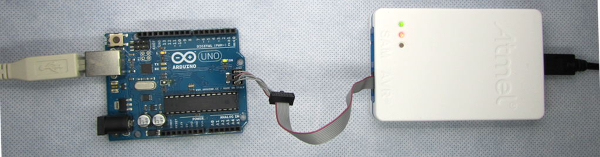
I have no idea what i have to do next, as my instructor sibu has explained me and said bring atml ice in my fablab and Arduino uno and connect as per the picture.The Atmel-ICE has both programming and debugging capabilities so my ISP can be programmed using instead of arduino with connection to atmel ice.

After that i was trying for programming following the process which has mentioned in the link
http://fab.cba.mit.edu/classes/863.16/doc/tutorials/fabisp_programming/.But i could not get success.

Following is the steps to run the device:
step1: Go to the unzipped firmware folder and open the terminal.
step2: type "make"
step3: type "make flash"
step4: type "make fuses"
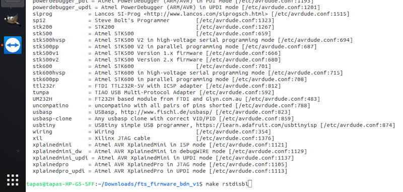
step5: type "make rstdisbl"
Next day one of my staff, Mr.Debasis, had an AVR USB programmer.

I removed the Ateml ice and connected avr usb programmer with my isp and tried with the firmware i have downloaded following the process as per the link of
fabisp programming. There I have modified the Makefile ATtiny 44 to ATtiny 45 and do the following activity.
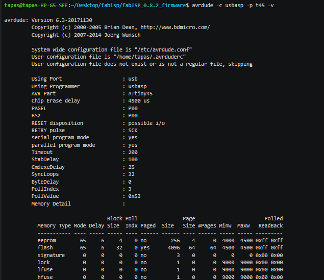
Here the isp is listing from pc through the avr. In makefile previously in place of usbasp atmel was there then changed usbasp.
AVRDUDE= avrdude -c usbasp -P usb -p


Then connected to the system which is not detected in pc . Then my instructor checked and verified and said to rectify the isp. The using firmware fabISP_0.8.2_firmware which is for ATtiny 44 but we are using ATtiny 45.
Here it needs to change the controller in our ISP ATtiny 45 to ATtiny 44. We are discussing with our instructor, not to change the controller, how can we reprogram the controller.

Remove the register and connect 20Mhz resonator
downloaded and unziped another firmawre from
https://github.com/Academany/FabAcademany-Resources/blob/master/files/firmware_45.zip
Then remove the 20 Mhz resonator and put again the two resistors then it works fine and fully successfully.

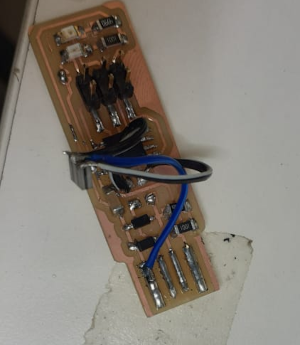
Programing other ISP using my programmer:-
Remove the USB AVR programmer i had connected my FabISP programmer for programming the other isp.

Now i have used my already programmed programmer which can communicate with the computer
and translates the messages to my friend deepak isp to make it a programmer.
Avrdude -c usbtiny -p t45 -v

"make flash"
"make fuses"
"make rstdisbl"


Successfully both are detecting to pc. Here two USBtiny is showing in the terminal after putting both programmers.

Resources:-
- http://heliosoph.mit-links.info/arduinoisp-reading-writing-fuses-atmega328p/
- http://fab.cba.mit.edu/classes/863.16/doc/projects/ftsmin/index.html
- http://fabacademy.org/2019/docs/FabAcademy-Tutorials/week04_electronic_production/mods.html
- http://fab.cba.mit.edu/classes/863.16/doc/tutorials/fabisp_programming/
- https://www.engbedded.com/fusecalc/
- https://components101.com/microcontrollers/attiny45-pinout-features-datasheet
https://www.component-en.com/products/EFJ-N1695J5B/13072649
Group assignment:-
Individual assignment:-
This machine can be used for PCB milling and drilling other than that this machine can also use for Cuttable Material of Modelling Wax, Chemical Wood, Foam, Acrylic, Poly acetate, ABS.
X, Y, and Z Operation Strokes203.2 (X) x 152.4 (Y) x 60.5 (Z) mm
Workpiece table size232.2 (X) x 156.6 (Y) mm
Distance From Collet Tip to TableMax, 130.75mm (5.15 in)
X-, Y-, and Z-Axis Drive System have stepping motor
Operating Speed is 6 - 1800mm/min
Spindle Motor is DC motor Type 380
Interface is USB
Cutting Tool Chuck with collet method
Spindle Rotation Speed can adjust i.e Adjustable 3000 - 7000 rpm
Dedicated AC adapter: AC 100-240 V ±10%, 50/60 Hz
The LEDs and their associated resistors are optional; the red LED lights when the target circuit is powered, and the green LED lights when the programmer is talking to the target.Solder the parts to the PCB, using the schematic and board imagebelow as a reference for component values and placement.Start with the most difficult parts (the ATtiny45) first, so you have the most access.Install the ISP header last, as it is large and can get in your way if you do it earlier.
https://www.component-en.com/products/EFJ-N1695J5B/13072649